Maverick Hoziel
AA-1 Yankee Electric Propulsion Conversion Project
Overview
This project explored the full engineering workflow required to replace the AA-1 Yankee’s original Lycoming O-235-C2C gasoline engine with a modern electric propulsion system. The objective was to understand performance impacts, battery requirements, and the redesign of avionics and electrical architecture needed to safely integrate an all-electric powerplant into a certified light aircraft.
My Role
As the electrical engineering lead on the team, I was responsible for:
-
Propulsion component selection
– Motor, inverter, battery modules, and contactor architecture -
Performance modelling
– Energy budgeting for all flight phases (takeoff, climb, cruise, descent, reserve) + analysis of flight range and fligh time. -
Avionics + electrical systems integration
– HV/LV architecture, logic-enable paths, CAN-bus communication, safety interlocks
Technical Details
1. Propulsion Component Selection
The first task was selecting an electric motor to replace the 115-HP (≈85 kW) Lycoming O-235-C2C engine [1].
To ensure sufficient performance margin and avoid under-powering the aircraft, we selected the MGM Compro BLDCin 200 kW motor [5], which provides:
- 200 kW peak power
- 150 kW continuous power
- An RPM range compatible with the AA-1 propeller, eliminating the need for a gearbox
Although this motor exceeds the power of the original Lycoming engine, excess thrust can be safely managed through inverter power limiting, preventing overspeed of flight control surfaces.
2. Battery Mass Allowance
The mechanical team determined that replacing the piston engine and associated systems resulted in a new empty weight of 798 lb, not including batteries. With a maximum takeoff weight (MTOW) of 1500 lb, and reserving 350 lb for passengers and baggage [2], the allowable battery mass is 160kg.
MGM Compro advertises up to 400 Wh/kg energy density [4], but a conservative 300 Wh/kg was used to account for non-cell mass. This yields a pack energy of:
\[E_{\text{pack}} = 160 \times 300 = 48\ \text{kWh}\]Only 80% usable energy is available in aviation applications for safety, giving:
\[E_{\text{usable}} = 0.8 \times 48 = 38.4\ \text{kWh}\]3. Performance Modeling
3.1 Takeoff + Climb Energy
Climb Energy from Potential Energy
\[E_{\text{climb}} = \frac{m g h}{\eta \times 3.6 \times 10^6}\] \[m = 1500\ \text{lb} = 681\ \text{kg}, \quad h = 8000\ \text{ft}, \quad \eta = 0.76\] \[E_{\text{climb}} = 5.95\ \text{kWh}\]Takeoff Energy
\[E_{\text{TO}} = \frac{1}{2} m V_{\text{TO}}^2 = 0.09\ \text{kWh}\]Total Takeoff and Climb Energy
\[E_{\text{climb+TO}} = 6.04\ \text{kWh}\]3.2 Reserve Energy
\[E_{\text{reserve}} = 60 \times \left(\frac{10}{60}\right) = 10\ \text{kWh}\]3.3 Cruise Energy + Duration
Cruise Energy
\[E_{\text{cruise}} = E_{\text{usable}} - E_{\text{climb+TO}} - E_{\text{reserve}}\] \[E_{\text{cruise}} = 38.4 - 6.04 - 10 = 22.36\ \text{kWh}\]Cruise Time
\[t_{\text{cruise}} = \frac{22.36}{60} = 0.373\ \text{h} = 22\ \text{min}\]Cruise Range
\[R_{\text{cruise}} = 117 \times 0.373 = 43.5\ \text{NM}\]4. Climb Range and Duration
Climb Time
\[t_{\text{climb}} = \frac{8000}{710[1]} = 11\ \text{min}\]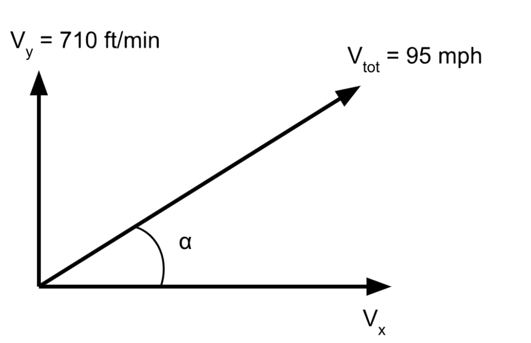
Climb Angle
\[\alpha = \arcsin\left(\frac{3.607}{42.47}\right) = 4.86^\circ\]Horizontal Velocity
\[V_{x,\text{climb}} = 95 \times \cos(4.86^\circ) = 94.66\ \text{mph} = 82.26\ \text{kt}\]Climb Range
\[R_{\text{climb}} = 82.26 \times 0.1833 = 15.1\ \text{NM}\]5. Descent Range and Duration
Approach speed range: 80–90 mph → use 85 mph midpoint [2].
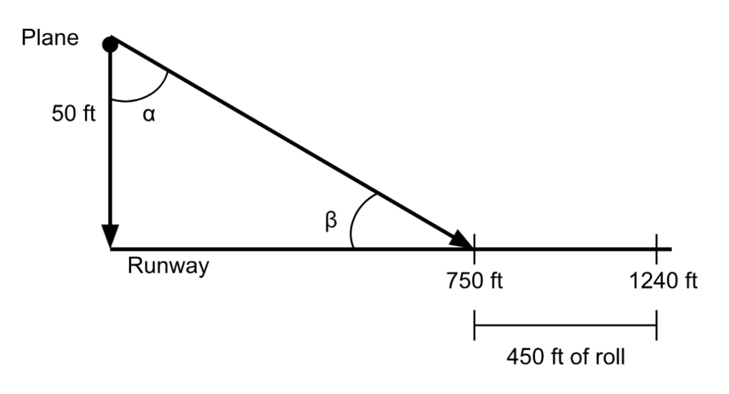
Descent Angle
\[\beta = \arcsin\left(\frac{50}{750}\right) = 3.82^\circ\]Horizontal Velocity
\[V_{x,\text{descent}} = 85 \times \cos(3.82^\circ) = 84.81\ \text{mph} = 73.70\ \text{kt}\]Vertical Velocity
\[V_{y,\text{descent}} = 85 \times \sin(3.82^\circ) = 498\ \text{ft/min}\]Descent Time
\[t_{\text{descent}} = \frac{8000}{498} = 16\ \text{min}\]Descent Range
\[R_{\text{descent}} = 73.70 \times 0.2666 = 19.65\ \text{NM}\]Verification
\[R_{\text{interpolated}} = 19.22\ \text{NM}\]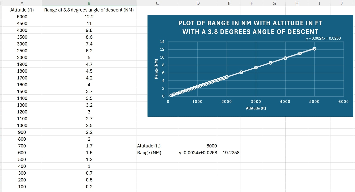
6. Total Mission Performance
\[R_{\text{total}} = R_{\text{climb}} + R_{\text{cruise}} + R_{\text{descent}}\] \[R_{\text{total}} = 15.1 + 43.5 + 19.5 = 78.1\ \text{NM}\] \[t_{\text{total}} = t_{\text{climb}} + t_{\text{cruise}} + t_{\text{descent}}\] \[t_{\text{total}} = 11 + 22 + 16 = 49\ \text{min}\]These results maintain a 10 kWh energy reserve, giving a conservative estimate of electric mission performance.
Avionics & Electrical Integration
1. Removal of Lycoming-Dependent Electrical Systems
The first step in redesigning the electrical system was identifying all components that depended on the Lycoming O-235-C2C engine. These components were highlighted in red on the original AA-1 electrical diagram [3]:
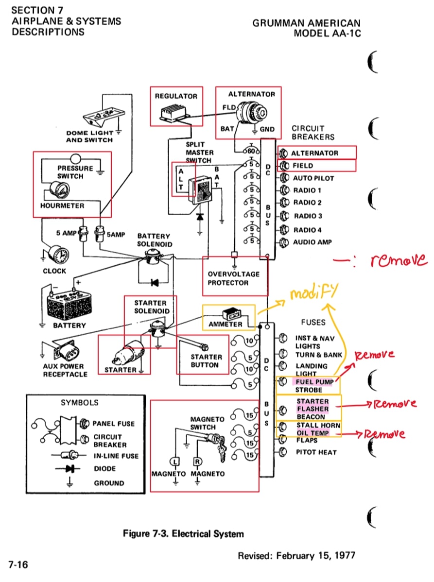
The following systems were removed entirely:
- Alternator and field circuits
- Voltage regulator
- Oil-pressure switch
- Overvoltage protection relay
- Starter solenoid and starter motor
- Magneto switch
- Fuel-pump, starter-flasher, and oil-temperature indicators
Because these systems relied on mechanical engine operation, they were eliminated for the electric-propulsion architecture.
2. High-Voltage (HV) Architecture
AAMCi V2-800 Contactor Module [8]
- Connects/disconnects the HV pack
- Performs pre-charge
- Manages main contactor logic
- Provides HV interlocks and surge protection
BMS-16Ai Battery Management System [4]
- Monitors cell voltages, temperatures, state of charge (SOC), and SOH
- Performs active balancing
- Authorizes HV activation only when conditions are safe
- Communicates with inverter and contactor via CAN
HBCi 400-800 High-Voltage Inverter [7]
- Converts HV DC to 3-phase AC for the BLDCin motor
- Provides motor control, torque commands, RPM feedback, and temperature monitoring
- Exchanges CAN messages with the BMS and contactor
- Accepts analog throttle input from the LV system
HV Master Switch (Honeywell TL-Series MIL-DTL-3950)
- Provides the pilot with a reliable manual arming switch
- Interrupts only the 12-V logic-enable lines (not HV power)
- Used because MGM COMPRO does not supply a cockpit arming switch
3. Reworked Electrical System Architecture
The completed electric-propulsion wiring architecture is shown below:
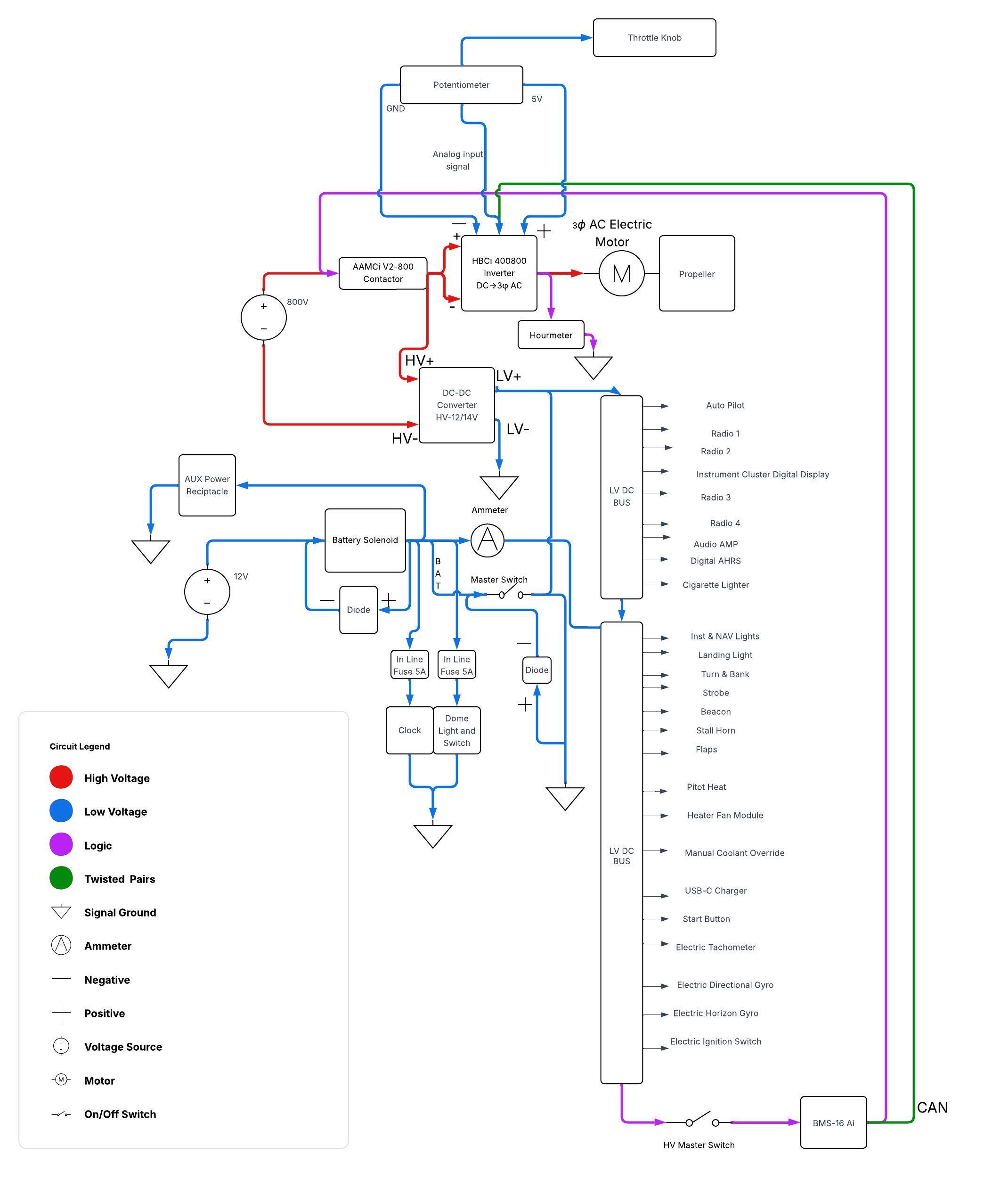
Circuit breakers are not shown in the reworked diagram for clarity; however, all loads on both the LV and HV buses are protected with appropriately sized breakers or fuses according to aviation electrical-wiring standards.
The system is divided into three coordinated subsystems:
3.1 Low-Voltage (LV) Bus
- Powered by the aircraft’s 12-V battery
- Feeds avionics, gauges, displays, and controls
- Supplies the analog throttle signal to the inverter
- Receives charging power from the DC-DC converter connected to the HV bus
3.2 High-Voltage (HV) Bus
- Feeds the inverter, contactor module, and propulsion motor
- Powers the DC-DC converter for LV charging
- Internal interlock lines ensure safe activation order
3.3 Logic & Control Layer (CAN Bus)
- Connects the BMS, inverter, and avionics display
- Handles SOC/SOH, temperature, RPM, torque commands, fault flags, and interlocks
The CAN bus is wired using twisted-pair conductors to reduce EMI, since HV switching and high-frequency inverter currents can introduce electrical noise affecting radios and avionics.
4. Cockpit Display Redesign
To maintain familiar pilot workload and ergonomics, the cockpit was redesigned to preserve original gauge functionality where possible. The original panel from [3] was marked with:
- Red → instruments removed entirely
- Yellow → instruments replaced with electric equivalents
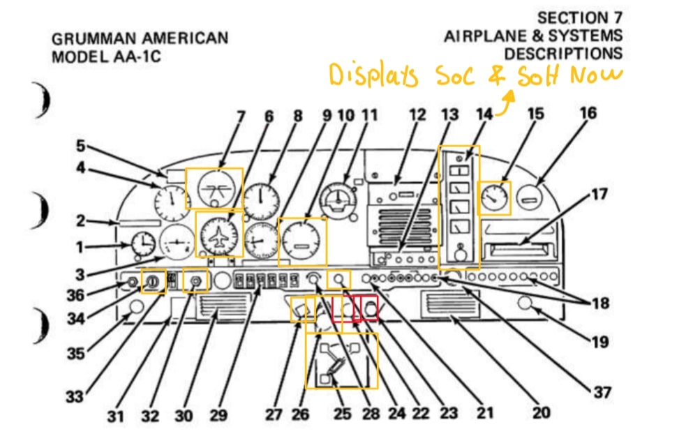
Examples:
- The tachometer becomes a digital RPM indicator driven from the inverter.
- Oil temperature and pressure gauges are replaced with SOC/SOH from the BMS and motor temperature from the inverter.
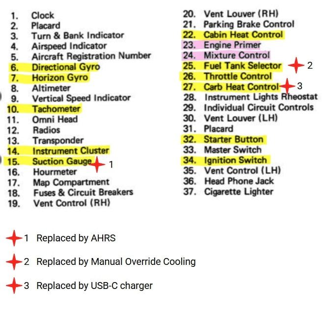
5. Reassigned Controls (Starred Components)
Some cockpit controls were repurposed to serve new functions under electric propulsion:
Suction Gauge → AHRS Display
- The suction gauge is replaced by an AHRS-driven attitude indicator.
- The AHRS module (e.g., Garmin GSU 25 or MGL AHRS-1) uses internal gyroscopes, accelerometers, and magnetometers.
- It operates independently from the propulsion system and outputs attitude data to the cockpit display.
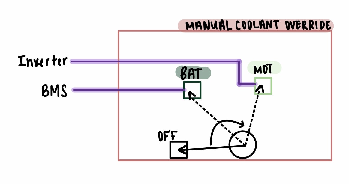
Fuel Tank Selector → Manual Coolant Override
This three-position selector (OFF-BATTERY-MOTOR) replaces fuel-tank switching.
It now allows the pilot to override automatic cooling and manually select whether coolant is routed to the battery or the motor, providing a safety-critical backup mode.
Carb Heat Control → Aviation-Grade USB-C Charger
The Carb Heat Control becomes unused in an electric aircraft.
Its panel location is repurposed for a shielded, aviation-grade USB-C power outlet.
This provides clean, RF-filtered power for portable avionics such as EFB tablets, handheld GPS receivers, or communication devices, improving cockpit usability without increasing pilot workload.
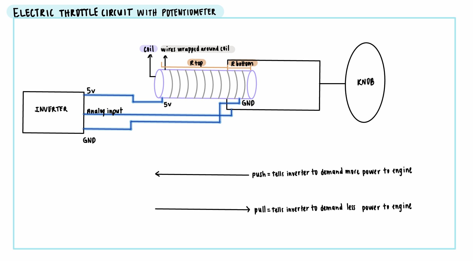
6. Throttle Potentiometer System
To preserve the pilot’s familiar throttle-push control, the mechanical throttle knob now drives a potentiometer-based voltage divider.
This produces an analog voltage:
\[V_{\text{out}} = V_{\text{in}} \times \left( \frac{R_{\text{bottom}}}{R_{\text{top}} + R_{\text{bottom}}} \right)\]This signal is read by the inverter’s analog-input channel and mapped to torque or power demand.
This architecture also enables software-level power limiting, ensuring the electric motor cannot exceed speeds that would exceed the aircraft’s structural control-surface limits.
[1] Grumman Owners & Pilots Association, AA-1/AA-1A/AA-1B/AA-1C POH Data.
[2] AA-1A Pilot Operating Handbook.
[3] AA-1C Pilot Operating Handbook.
[4] MGM Compro Battery Systems, https://mgm-compro.com/ess-batteries/
[5] MGM Compro BLDCin 200 kW Motor, https://mgm-compro.com/electric-motor/mgm-bldcin-200kw/
[6] MGM Compro Propulsion Systems Overview, https://mgm-compro.com/eps-propulsion-systems/
[7] MGM Compro HBCi 400/800 Inverter, https://mgm-compro.com/controllers-inverters-escs/hbci-400800/
[8] MGM Compro AAMCi Series Contactor, https://mgm-compro.com/electronics-contactors/aamci-series-v2-800/
[9] Climb Rate Data, Manufacturer Performance Tables.
[10] Hepperle, M., Electric Flight, DLR.
[11] Transport Canada Advisory Circular AC 700-028.